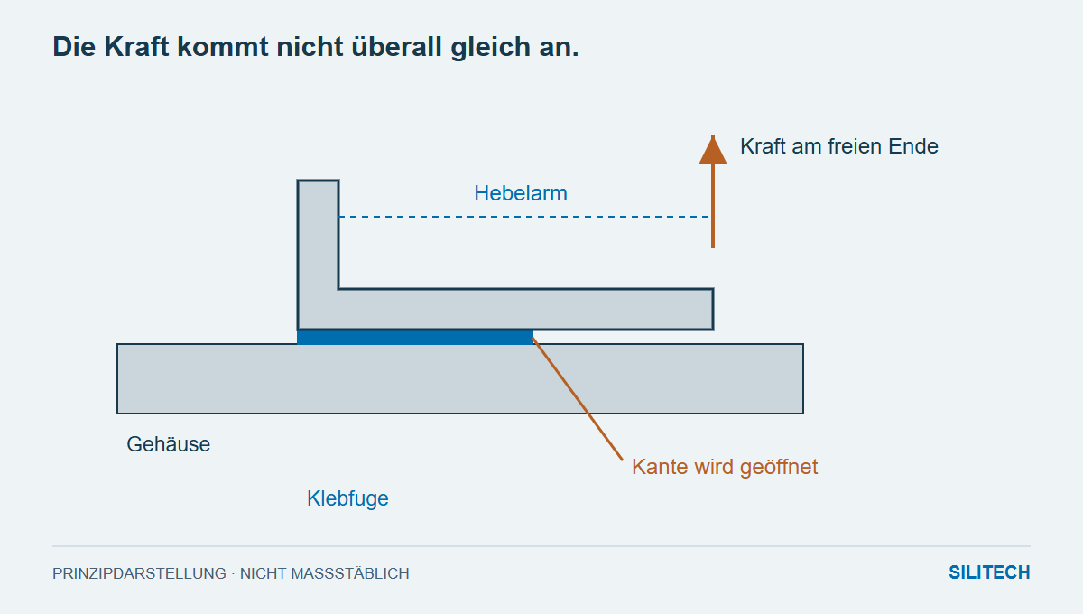
An angle bracket is glued over a large area to a metal housing. A cable pulls on the free end. Despite the large adhesive surface, an edge opens up. A first glance at the adhesive alone doesn't tell the whole story: the shape of the bracket distributes the force unfavorably.
Therefore, a sketch is drawn first to determine the correct application. Where does the force act, in which direction does it work, and what is its lever arm relative to the adhesive point?
Shearing and opening place different stresses on the joint
Under predominantly parallel loading, the surfaces transmit the force differently than when prying open an edge. Peeling or splitting stresses can concentrate in a limited area. Permabond recommends limiting such loads through design and distributing the load more favorably.
With a shorter free leg, the angle can reduce the lever arm. A different force application point or additional structural support can also be relevant. Which solution is suitable depends on the entire component. Simply adding more surface area at a less effective point does not replace this consideration.
Metal is the base, the surface is the contact
An aluminum housing can be bare, anodized, or painted. With a coating, the adhesive initially bonds to this layer. Its adhesion to the metal then becomes part of the load path.
The intended surface condition is therefore used for the sample. Grinding off a coating is a separate process decision and must be compatible with manufacturing and component requirements. A well-adhering sample on bare sheet metal does not guarantee the subsequent painted joint.
The joint must be able to be created
Spacing and fixing are crucial aspects of the design. Two adhesives may appear similar upon application but still require different processing steps. With a two-component system, the mixture and curing time must be precise; other systems require, for example, heat or a specific contact mechanism.
The device not only holds the part in place, but also determines its position and thus the actual joint. An angled clamping angle is a different design than the parallel connection shown in the drawing.
The component test contains the critical edge
A material comparison using overlapping sheet metal strips can aid in the preliminary selection. The clamping test introduces the actual force application. It is designed to capture the critical edge and the intended secondary loads, such as cable tension during assembly.
After a fracture, the load and both surfaces are considered together. Does a coating detach, does the interface separate, or does the adhesive fail? The next targeted modification follows from this.
The adhesive works effectively in a suitably designed bond. The sketch with the force arrow is the first technical step towards that.
Two practical questions
Does a larger adhesive surface always help proportionally?
No. With unfavorable force application or an opening edge, the stress is not distributed evenly. The position and geometry of the surface are also relevant.
What should be considered besides the operational load?
Predictable stresses during assembly, transport, and servicing. A handle on the cable or holder may have a different direction and leverage than during normal operation.
To deepen the connection
The current product documentation is decisive for processing.