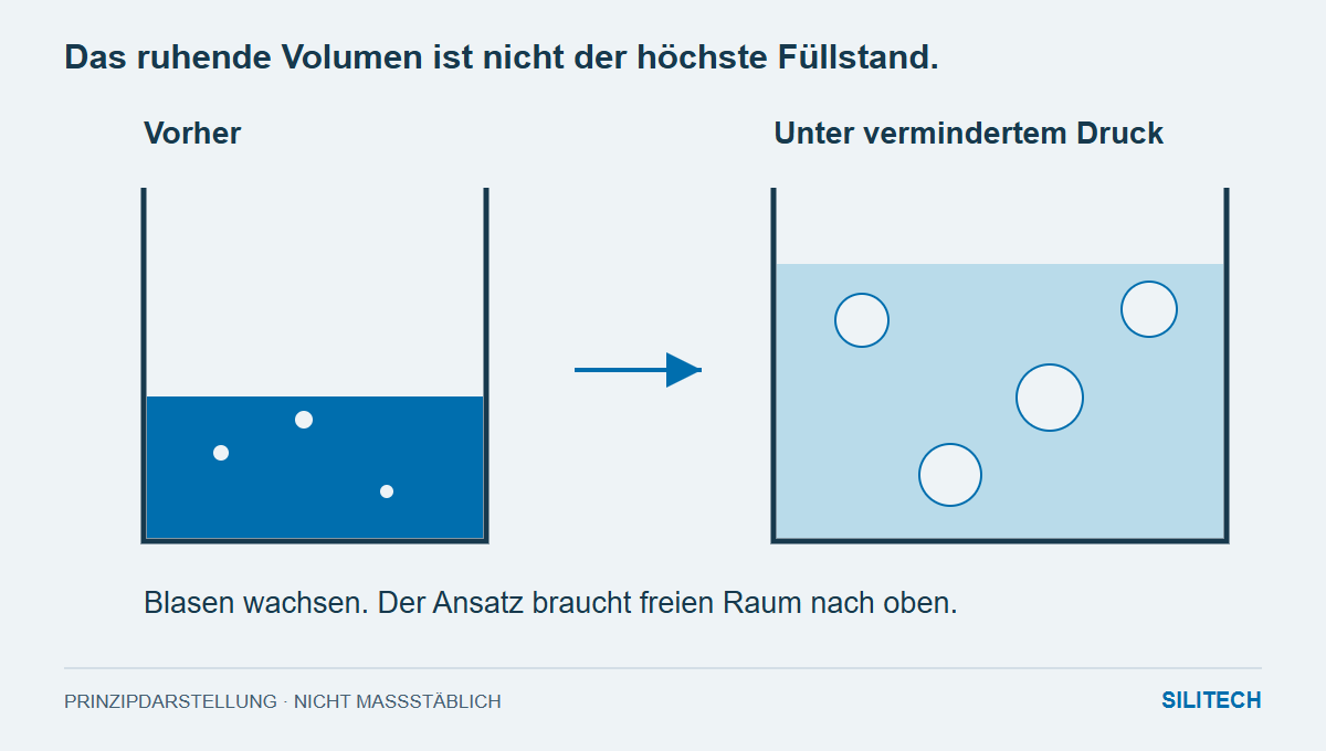
The beaker is half full. As soon as the vacuum is applied, the mixture rises sharply. The free space, which just moments ago seemed generous, suddenly becomes scarce.
Under reduced pressure, trapped gas bubbles expand. As they rise and escape to the surface, the material can occupy significantly more space than before. Therefore, the choice of container must take this degassing process into account.
Width helps – height is still needed
For BLUESIL RTV 141 A & B, Elkem recommends a container with a large diameter relative to its height to facilitate degassing. At the same time, the instructions require sufficient height to accommodate the rising material.
A wider container shortens the path through the liquid for the same fill level and offers more free surface area. However, a rim that is too low can still lead to overflow. Therefore, "as flat as possible" would be an incomplete fulfillment of the requirement.
A general free space factor for all resins and silicones cannot be derived from this. Viscosity, air ingress, quantity, and process conditions all affect the behavior. Therefore, the observed maximum value should be part of a suitable product and system test.
The process begins at the agitator
Before degassing, the preparation and combination of the components are determined. For RTV 141, the instructions specify stirring the individual components followed by a low mixing speed to limit air entrainment.
Stirring faster can change the initial conditions for the vacuum stage. Changing the beaker shape, batch size, and mixing method might yield a different result, but it reveals little about the underlying cause.
A smooth surface does not necessarily mean a bubble-free component
After the chamber, the material is transferred and poured. During this process, air can be introduced again or trapped within the geometry. The RTV-141 instructions recommend slow, even pouring; for thicker castings, the application should begin at the lowest point of the volume to be filled.
For an electronics housing, the filling path is therefore crucial. The material must reach the intended areas while the displaced air can escape. Good degassing cannot compensate for a blocked air path within the component.
The appropriate vessel connects all three steps
It allows for the intended mixing, reliably contains the rising liquid, and then enables a controlled pour. A cup that works well in the chamber but creates significant turbulence during pouring only solves part of the problem.
For clarification, the batch size, vessel dimensions, and maximum level during degassing are helpful. Together with the pouring path, this creates a comprehensible process. The vacuum pressure and operation depend on the specific product and system requirements; the vessel diagram is not a universal process setting.
Two practical questions
Can I use the cup up to its normal fill volume?
The static level does not account for the rise under vacuum. The container requires the free space necessary for the material and the flow.
Why do defects remain in the component despite degassing?
During the pouring process, air can be reintroduced or trapped in areas that have not been vented. Therefore, the degassing step and the filling geometry are considered separately.
Mentioned in the article
BLUESIL RTV 141 A + B (1.1 kg kit) ↗To deepen the connection
Technical Sources and Conditions
The current product documentation is decisive for processing.